Winding Resistance Meter: Complete Guide
Everything You Need to Know About Transformer Winding Resistance Testing
From basic principles to advanced applications - your comprehensive guide to selecting and using winding resistance meters for transformer diagnostics in India.
Quick Navigation
What is a Winding Resistance Meter?
A winding resistance meter (also called a transformer winding resistance meter, micro-ohm meter, or DLRO meter - Digital Low Resistance Ohmmeter) is a specialized electrical testing instrument designed to measure the DC resistance of transformer windings, motor coils, generator windings, and other low-resistance electrical components.
Unlike standard multimeters that can only measure resistances down to 1 ohm with limited accuracy, winding resistance meters can precisely measure resistances from 1 microohm (μΩ) to several thousand ohms with accuracy typically better than ±0.2%.
💡 Key Point
Transformer windings typically have resistances in the milli-ohm (mΩ) range - far too low for standard multimeters to measure accurately. Winding resistance meters are specifically engineered for this ultra-low resistance measurement requirement.
What Does a Winding Resistance Meter Measure?
The meter measures the DC resistance of:
- Power transformer windings (HV, LV, tertiary)
- Distribution transformer windings
- Motor windings (3-phase, single-phase, DC motors)
- Generator stator windings
- Busbar connections
- Circuit breaker contacts
- Cable splices and joints
- OLTC (On-Load Tap Changer) contacts
How Does a Winding Resistance Meter Work?
The operating principle of a winding resistance meter is based on Ohm's Law:
Where R = Resistance (Ω), V = Voltage (V), I = Current (A)
The Measurement Process
Here's how the meter performs a measurement:
1️⃣ Current Injection
The meter injects a known, stable DC current (ranging from 0.1mA to 10A) through the winding under test.
2️⃣ Voltage Measurement
Precision instruments measure the voltage drop across the winding caused by the injected current.
3️⃣ Resistance Calculation
The microprocessor calculates resistance using R = V/I and displays the result in μΩ, mΩ, or Ω.
Why Use DC Current?
DC current is used rather than AC for several important reasons:
- No impedance effects: AC measurements would include inductive reactance, which varies with frequency
- Measures pure resistance: DC gives the true conductor resistance without reactive components
- Comparable results: Industry standards (IEC 60076-1) specify DC resistance measurements
- Baseline for other tests: DC resistance serves as reference for load loss calculations
The 4-Wire Kelvin Measurement Method
Professional winding resistance meters use the 4-wire Kelvin method (also called a Kelvin bridge or 4-terminal measurement) to achieve high accuracy when measuring very low resistances.
Why 4-Wire is Superior to 2-Wire Measurement
⚠️ The 2-Wire Problem
With 2-wire measurement, the test lead resistance (typically 10-50mΩ per lead) is included in the measurement. When measuring transformer winding resistances of 1-10mΩ, the lead resistance can introduce errors of 50-500%!
2-Wire Measurement
Current path: Source → Lead 1 → DUT → Lead 2 → Source
Voltage measured: Across entire circuit including leads
Result: R_measured = R_DUT + R_lead1 + R_lead2
Problem: Lead resistance adds to reading
4-Wire Kelvin Measurement
Current path: Source → C+ → DUT → C- → Source
Voltage measured: Separate high-impedance path (P+, P-) directly across DUT
Result: R_measured = R_DUT only
Advantage: Lead resistance eliminated
How 4-Wire Measurement Eliminates Lead Errors
The 4-wire method uses four separate connections:
- C+ and C- (Current terminals): High current path for injecting test current
- P+ and P- (Potential/Voltage terminals): Separate sensing path connected directly to the test object
Since the voltage sensing circuit has very high impedance (mega-ohms), virtually no current flows through the P+ and P- leads. With no current flow, there's no voltage drop across these sensing leads (V = I × R, where I ≈ 0). Therefore, the meter measures only the voltage drop across the device under test, completely eliminating lead resistance errors.
🔬 Industry Standard in India
All major testing laboratories and utilities in India use 4-wire Kelvin measurement for transformer acceptance testing and periodic diagnostics. This is mandated by IEC 60076-1 standards. Learn more about why Indian labs prefer this method →
Why Winding Resistance Testing is Critical
Winding resistance measurement is one of the most important diagnostic tests for transformers and rotating machines. Here's why it's essential:
🎯 Fault Detection
Detects loose connections, broken conductors, poor solder joints, OLTC contact wear, and winding deterioration before they cause catastrophic failure.
⚡ Safety Assurance
Identifies dangerous conditions like overheating connections that could lead to fires, explosions, or electrical hazards in substations.
📊 Performance Baseline
Establishes baseline values for comparison during periodic testing, enabling trend analysis and predictive maintenance strategies.
✅ Standards Compliance
Required by IEC 60076-1 for factory acceptance tests and by utilities for periodic transformer condition assessment in India.
Common Faults Detected by Winding Resistance Testing
- Loose or poor connections: Resistance increases at connection points
- Broken strands in parallel conductors: Overall resistance increases
- OLTC contact wear: Transition resistance between tap positions changes
- Shorted turns: Resistance decreases compared to baseline or other phases
- Winding deterioration: Resistance drift over time indicates aging
- Phase imbalance: Resistance difference >2% between phases indicates problems
- Manufacturing defects: Wrong wire gauge, incorrect turns, poor connections
Read our detailed guide on common faults detected using winding resistance testing →
Applications of Winding Resistance Meters
Power Transformers
Testing HV, LV, and tertiary windings in power and distribution transformers from 100 kVA to 500 MVA. Critical for factory acceptance testing and commissioning.

OLTC Diagnostics
Dynamic resistance measurement (DRM) during tap changer operation reveals contact wear, timing issues, and transition resistance problems.
Motors & Generators
Measuring stator and rotor winding resistance in induction motors, synchronous generators, and DC machines for fault diagnostics and efficiency testing.
Additional Applications
- Circuit breaker contact resistance: Verifying proper contact pressure and condition
- Busbar joint resistance: Testing welded, bolted, and compression joints
- Cable splice resistance: Quality verification of cable splices and terminations
- Reactor and choke windings: DC resistance measurement for quality control
- Current transformer secondaries: Burden calculation and fault detection
Key Specifications to Consider
When selecting a winding resistance meter, these specifications determine its suitability for your application:
1. Test Current Range
The maximum DC current the meter can output. Higher currents provide faster, more stable measurements on large transformers:
- 2A meters: Suitable for distribution transformers up to 100 MVA, motors, generators
- 10A meters: Required for large power transformers (100-500 MVA), faster measurements
- Higher (20A, 40A, 100A): Specialized applications, very large transformers
2. Measurement Range
The span of resistance values the meter can measure:
- Minimum: Typically 1μΩ (microohm) for contact resistance
- Maximum: Usually 2kΩ to 20kΩ for tertiary windings
3. Accuracy
Specified as ±(% of reading + number of digits):
- ±(0.1% + 2 digits): High-precision laboratory meters
- ±(0.2% + 2 digits): Standard for professional field testing (e.g., Innova I-63C)
- ±(0.5% + 2 digits): Basic models, acceptable for routine testing
4. Measurement Speed
Time required for reading to stabilize:
- Higher test currents = faster measurements (overcome inductive effects quicker)
- Large transformer windings can take 10-60 seconds to stabilize
- Auto-demagnetization features speed up repeat measurements
5. Additional Features
- Temperature compensation: Automatically corrects readings to standard temperature (20°C or 75°C)
- Data storage: Internal memory for saving test results
- PC connectivity: USB or RS-232 for downloading data and report generation
- Battery operation: Portable testing without AC power (e.g., MO-6310+)
- Automatic discharge: Safely discharges inductive energy after measurement
- Dynamic resistance (DRM): For OLTC testing during tap change operations
How to Choose the Right Winding Resistance Meter
Selecting the appropriate meter depends on your specific application requirements. Here's a decision framework:
Step 1: Determine Your Primary Application
Distribution Transformers
Typical Range: Up to 100 MVA
Recommended: 2A meter
Example: Innova I-63C
Power Transformers
Typical Range: 100-500 MVA
Recommended: 10A meter
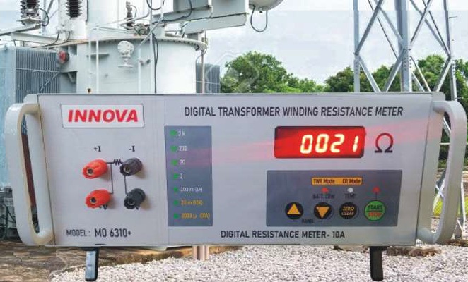
Example: Innova MO-6310+
Motors & Generators
Typical Range: Various sizes
Recommended: 2A meter
Example: Innova I-63C
Step 2: Consider Required Features
- Need OLTC testing? → Choose model with Dynamic Resistance Measurement (DRM)
- Working in remote locations? → Battery-operated model (e.g., MO-6310+)
- Need detailed reports? → Model with PC connectivity and software
- Testing at various temperatures? → Temperature compensation feature is essential
- Budget-conscious? → 2A portable meter offers excellent value
Step 3: Evaluate Total Cost of Ownership
Consider beyond purchase price:
- Calibration costs: Annual calibration required for compliance
- Test lead quality: Heavy-duty leads reduce contact resistance errors
- Training requirements: Simpler interfaces reduce training time
- Local support availability: Important for repairs and technical assistance
- Spare parts availability: Especially for international brands
Read our comprehensive buyer's guide for detailed selection criteria →
Winding Resistance Meter Comparison
Compare popular models available in India
| Feature | Innova I-63C | Innova MO-6310+ | Typical Import Brand |
|---|---|---|---|
| Max Test Current | 2A | 10A | 10A - 100A |
| Measurement Range | 1μΩ to 19.99kΩ | 2mΩ to 2000Ω | 1μΩ to 200kΩ |
| Accuracy | ±(0.2% + 2 digits) | ±(0.5% + 2 digits) | ±(0.1% + 2 digits) |
| Measurement Method | 4-wire Kelvin | 4-wire Kelvin | 4-wire Kelvin |
| Power Supply | AC 220V | Rechargeable Battery | AC or Battery |
| Portability | Portable (2 kg) | Portable (5.9 kg) | Varies (5-15 kg) |
| Application | Up to 100 MVA | Up to 500 MVA | All transformer sizes |
| Temperature Range | -10°C to +50°C | -15°C to +55°C | Varies |
| Data Storage | Manual recording | Manual recording | Yes, extensive |
| PC Connectivity | None | None | Yes (USB/Ethernet) |
| Price in India | ₹6,500 | ₹75,000 | ₹2,00,000+ |
| Best For | Distribution transformers, motors, routine testing | Power transformers, field testing, OLTC diagnostics | Labs, manufacturers, comprehensive testing programs |
Innova I-63C
Best Value for Distribution Transformers
Ideal for utilities, industrial maintenance, and motor testing. 2A test current handles transformers up to 100 MVA with excellent accuracy.
View DetailsInnova MO-6310+
Professional 10A Power Transformer Tester
Battery-powered for field testing of large power transformers. 10A current provides fast, stable measurements on 100-500 MVA transformers.
View DetailsBasic Testing Procedure
While specific procedures vary by equipment and transformer type, here's the general process for winding resistance testing:
1. Safety First
De-energize transformer, verify isolation, ground all windings to discharge residual voltage, check for permits and clearances.
2. Equipment Setup
Connect test leads using 4-wire method: current leads (C+, C-) to bushing terminals, voltage leads (P+, P-) as close as possible to connection point.
3. Perform Measurement
Select appropriate test current, initiate test, wait for stable reading (typically 10-60 seconds), record resistance value and ambient temperature.
⚠️ Important Considerations
- Temperature matters: Winding resistance changes ~0.4% per °C. Always record temperature and apply corrections.
- Wait for stability: Large transformer windings have high inductance. Readings may drift for 60+ seconds.
- Tap position: Always note OLTC tap position. Different taps have different resistances.
- Connection method: For delta connections, measure line-to-line. For star, measure phase-to-neutral.
Read our detailed step-by-step testing procedure guide →
Interpreting Results
After measurement, compare results against:
- Baseline values: Factory test reports or previous test results
- Between phases: Imbalance >2% warrants investigation
- Calculated values: Based on winding design (turns, wire gauge, length)
- Standards limits: IEC 60076-1 acceptance criteria
Common Testing Challenges & Solutions
Drifting Readings
Causes: Poor connections, temperature changes, residual magnetism, inadequate test current
Solutions: Clean contacts, use higher test current, demagnetize core, allow sufficient stabilization time
Inconsistent Results
Causes: Test lead resistance variations, connection point changes, temperature fluctuations
Solutions: Use 4-wire method, maintain consistent connection points, apply temperature corrections
Safety Concerns
Causes: Improper isolation, residual charge, inductive kickback
Solutions: Follow lockout/tagout, ground before connecting, use auto-discharge meters
Expert Resources & Guides
Comprehensive articles to deepen your knowledge
📖 Testing Guides
🔍 Troubleshooting
Frequently Asked Questions
Ready to Test Your Transformers?
Explore our professional winding resistance meters for accurate transformer testing
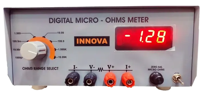
Innova I-63C
2A Portable Winding Resistance Meter
Perfect for distribution transformers, motors, and generators. High accuracy ±(0.2% + 2 digits), compact design, excellent value at ₹6,500.
View I-63C Details
Innova MO-6310+
10A Professional Battery-Operated Tester
For large power transformers and field testing. 10A test current, Li-Ion battery, internal memory, USB connectivity. ₹75,000.
View MO-6310+ DetailsSummary
Winding resistance meters are essential tools for transformer diagnostics, maintenance, and commissioning. Understanding the 4-wire Kelvin measurement principle, proper test procedures, and result interpretation enables effective fault detection and equipment condition assessment.
When selecting a winding resistance meter, match the test current capability to your application - 2A for distribution transformers and motors, 10A for large power transformers. Consider additional features like battery operation, OLTC testing capability, and data logging based on your specific requirements.
Regular winding resistance testing as part of a comprehensive transformer maintenance program helps detect faults early, prevents costly failures, ensures safety, and extends equipment life.
📞 Need Help Choosing?
Our team of transformer testing experts is here to help you select the right winding resistance meter for your application. Contact us for personalized advice →